Nodes
Nodes are the building blocks of Video Vision business logic. To create a functioning customer solution, the nodes in the flow builder need to be correctly placed, linked, and configured.
Each node has a specific purpose and use. You will find each node’s functionality below.
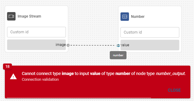
When you connect nodes, the input and output must be the same value type.
The exceptions to this rule are the ‘any’ and ‘undefined’ values - ‘any’ accepts all inputs, while ‘undefined’ changes based on the connected input.
Inputs
Input nodes serve as data entry points of your flow. They can represent input sources like cameras and relays or custom inputs, such as text or a number.

Boolean Input
Emits one of two possible values (i.e., True or False) into the flow from an external connection (e.g., an ADAM-6060, or from a different flow).
Outputs | Description | Type |
Bool | Returns a boolean value based on the connection. | Bool |

Current Date & Time
Outputs the current date and time.
Outputs | Description | Type |
Datetime | Returns the current date and time. | Datetime |

Custom Image
Outputs a solid color image with a custom color and resolution.
Configuration
Color
Specifies the color of the image.Height
Sets the image height.Width
Sets the image width.
Outputs | Description | Type |
Image | Returns the configured image. | Image |

Image Stream
Outputs individual images from a camera into the flow for further processing.
Outputs | Description | Type |
Image | Returns individual frames from the camera stream. | Image |
Enter a custom name for this node to ensure that you pair with the appropriate device later in the set up process.

Number
Outputs a custom numeric value based on the node configuration.
Configuration
Number value
Configures the number that the node delivers as output.
Number Input
Returns a number from an external connection or another flow.
Outputs | Description | Type |
Number | Returns a number based on the connected source. | Number |

Polygon
Outputs a custom polygon based on the configuration.
Configuration
Polygon coordinates
Specifies the points used to form the shape in the following format: x1,y1;x2,y2;...;xn,yn.
X coordinates specify points on the horizontal axis (from the left border) and Y coordinates specify points on the vertical axis (from the top border). The coordinate units represent a fraction of the image (0.1 = 10% from the image border).
Outputs | Description | Type |
Polygon | Returns a custom polygon. | Polygon list |

Schedule
Represents the timetable specified in the Scheduler section of the Video Vision application.
Outputs | Description | Type |
Datetime | Returns a signal every time the associated schedule is triggered. | Datetime |
Use a specific label for this node to ensure that you pair with the appropriate device later in the set up process.
Switch
Outputs a true or false value based on the node configuration.
Configuration
Boolean value
Configures the bool value to be output by the node.
Outputs | Description | Type |
Output | Returns a true or false value based on the node configuration. | Bool |

Text
Outputs custom text based on the node configuration.
Configuration
String value
Configures the text to be output by the node.
Outputs | Description | Type |
Output | Returns the text configured in the node. | String |
Image processors
Image processors modify or transform images in order to make them more suitable for a given solution.

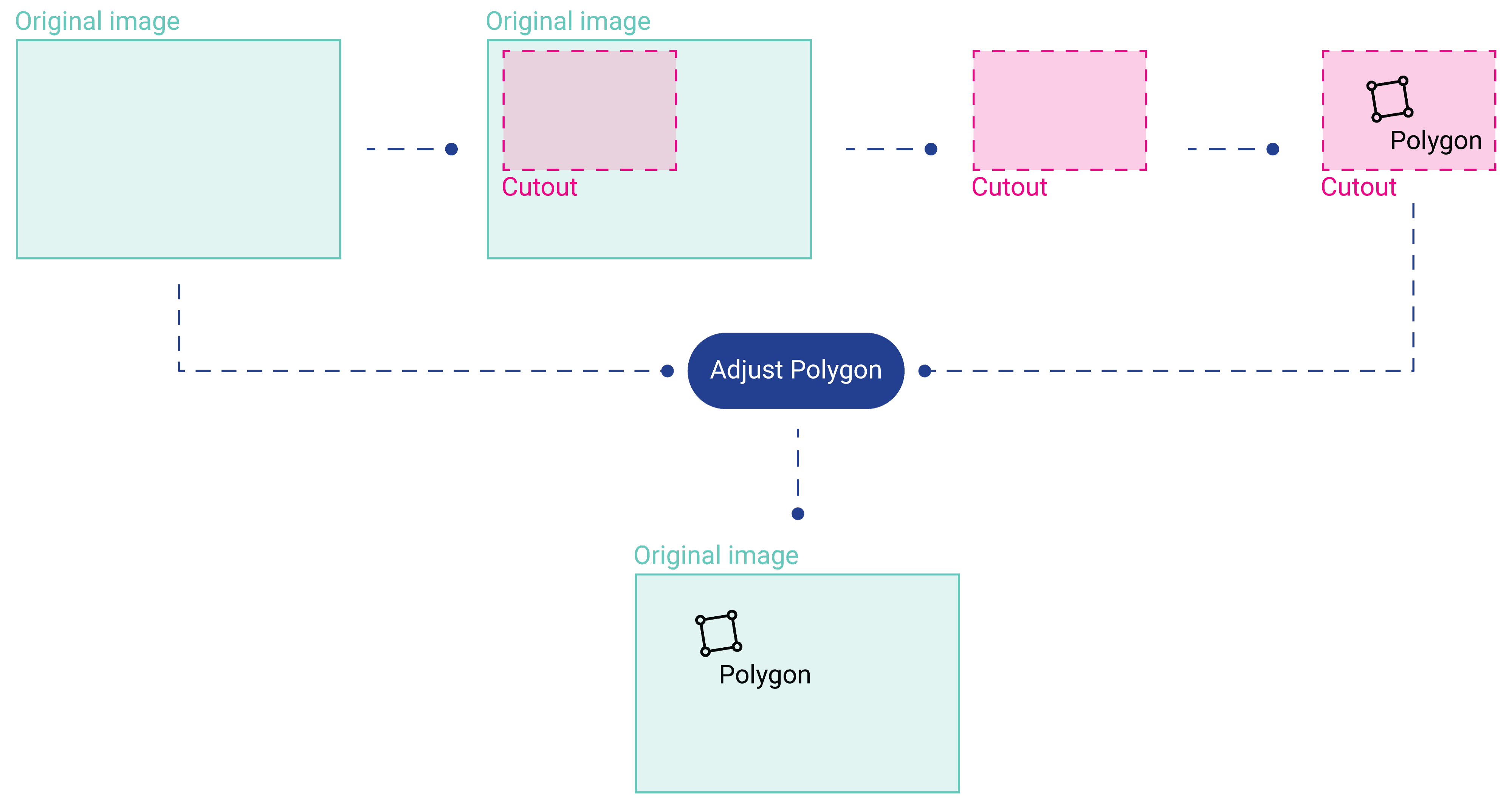
Adjust Polygons To Original Image
Adjusts polygon coordinates detected in a section of an image so they can be correctly displayed on the region of the original image. It handles rescaling and shifting to ensure that the polygon’s position reflects the entire image rather than just the subregion.
This functionality is essential when rescaling images for purposes such as neural network training while needing to overlay the detected polygons on the original image.
Below is a visual representation of the process:
Inputs | Description | Type |
|---|---|---|
Detected polygons | List of polygons found in the subregion that need to be remapped to the full image. | Polygon List |
polygon_roi | The subregion (“cutout”) of the image. | Polygon |
Outputs | Description | Type |
Adjusted polygons | Polygons with their coordinates transformed to align with the original image. | PolygonList |

Crop Image
Crops the image on each side and then outputs it modified.
Configuration
Dimensionless crop
Crops by a fraction of the image. For example, to crop an image by 10% from each side, you enter a 0.1 value for each respective side.Pixel crop
Crops the image by a specific pixel count. For example, to crop an image width by 200 pixels, you crop it by 100 pixels from the left and right side, respectively.
Inputs | Description | Type |
|---|---|---|
Image | Receives images. | Image |
Outputs | Description | Type |
Cropped image | Returns images cropped according to the configuration | Image |

Merge Images
The Merge Images node arranges multiple images into a single image output. The layout of the final image depends on the node configuration.
Configuration
Layout
Determines the layout of the merged images.Horizontal
Arranges the images in a horizontal (left-to-right) pattern.Vertical
Arranges the images in a vertical (top-to-bottom) pattern.Quad
Arranges the images in a 2 x 2 square pattern. This option is only possible for four images.
Number of inputs
The number of images to be merged.
Inputs | Description | Type |
|---|---|---|
Image 1 | First image input | Image |
Image 2 | Second image input | Image |
Outputs | Description | Type |
Image | Returns the merged image. | Image |
All the image inputs must have the same aspect ratio (e.g., 4:3, 16:9).
This node can only be used with multiple cameras or lenses set up in the Devices section.

Overlay Heatmap
The Overlay Heatmap node overlays a heatmap onto an image, allowing you to visualize data directly within the image context. The node includes options to adjust the heatmap’s opacity and select from several predefined color gradients.
A heatmap is a data matrix where each pixel is assigned a value. These values can be mapped to a color gradient to visualize the heatmap, highlighting areas of interest like potential anomalies.
In computer vision, heatmaps help identify defects or irregularities by overlaying these gradients onto an image, making patterns easier to spot.
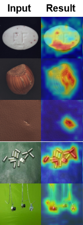
Heatmap overlay example
Inputs | Description | Type |
|---|---|---|
Image | The original input image. | Image |
Heatmap | The heatmap image. | Image |
Outputs | Description | Type |
Overlayed heatmap image | Returns the composite image that overlays the heatmap on the original image. | Image |
The heatmap is resized to match the dimensions of the original image. As a result, the output image will also have the same size as the original.
Configuration
Heatmap gradient colours
Choose a predefined gradient based on your specific application. Refer to the information below.Heatmap opacity
Adjust the Heatmap's visibility0: Fully transparent (invisible heatmap).
100: Fully opaque (solid color).
⚠️ Setting the opacity to 100 entirely covers the original image.
Color Gradients
To optimize how heatmaps are displayed on the video vision dashboard, we have selected several industry standard heatmaps.
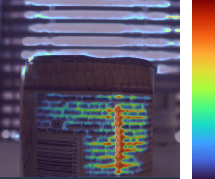
Turbo
Use case: Real-time defect identification with vibrant colors and perceptual uniformity.
Ideal for: Quick identification and differentiation of defects in live production lines.
Avoid: Scenarios where viewers might have color vision deficiencies.
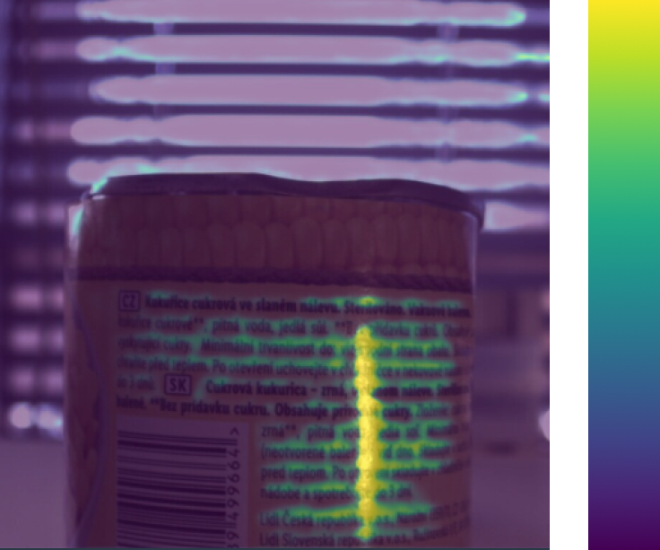
Viridis
Use case: Reliable and consistent defect analysis
Ideal for: Reviewing defect trends and general-purpose visualisations that are perceptually uniform, intuitive & accessible to all users.
Avoid: When vibrant colors or color differentiation is needed.

Cividis
Use case: Accessible visualizations for applications where grayscale compatibility and colorblind-friendly palettes are required
Ideal for: Grayscale conversion & detecting structural defects like cracks or dents.
Avoid: Scenarios requiring vibrant, non-linear color mapping.
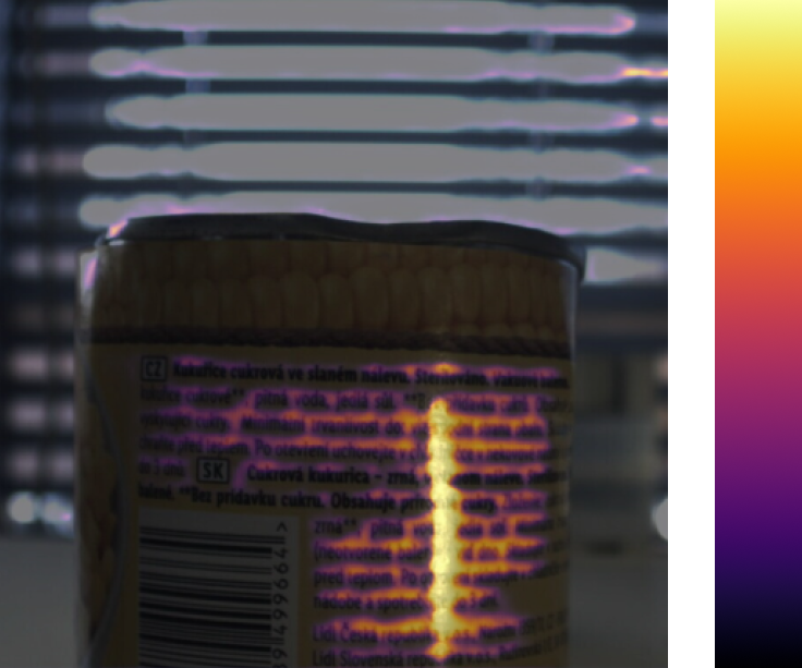
Inferno
Use case: Highlighting small defect features in dark imagery. Ideal for detecting subtle contrasts, such as minor temperature variations, hairline cracks, or slight discolorations.
Ideal for: Thermal imaging or low-light inspection scenarios.
Avoid: If the production floor has bright lighting, as the dark-to-light gradient might lose its effectiveness.
Polygon Crop
Crops the image to the area of a polygon.
Inputs | Description | Type |
|---|---|---|
Polygon | Determines the area to be cropped from the original image. | Polygon |
Image | The image intended for cropping. | Image |
Outputs | Description | Type |
cropped_mage | Returns the cropped image. | Image |

Region of Interest
The Region of Interest node allows you to filter or identify polygons based on their presence in specific areas of the image. For example, suppose a portion of the camera image displays a busy area with people. In that case, it might interfere with the detection accuracy or cause false positives, so the node would be used to detect only the area of production that doesn’t have people in it.
Configuration
Check method
The method by which it is determined whether the polygon is inside the region of interest or not.Center - The center of the polygon must be inside the Region of interest.
Region of interest polygon
The coordinates of the polygon are arranged in the following format: x1,y1;x2,y2;...;xn,yn. Where 'x' is the horizontal coordinate (from left image border), and 'y' is the vertical coordinate (from the top image border). The coordinates are expressed as a fraction of the image (0.1 = 10% from the image border).
Inputs | Description | Type |
|---|---|---|
Polygons | Receives polygons. | Polygon list |
Outputs | Description | Type |
Inside | Polygons inside the region of interest. | Polygon list |
Outside | Polygons outside the region of interest. | Polygon list |
Region of interest | The edges (polygon) of the Region of interest. | Polygon list |

Resize image
The Resize Image node changes the image size to the configured resolution. This can be used to resize the image for the dashboard, to match the resolutions accepted by the AI model, or for reporting purposes.
Configuration
Height
Sets the image height.Width
Sets the image width.
Inputs | Description | Type |
|---|---|---|
Image | Receives images. | Image |
Outputs | Description | Type |
Resized image | Returns the resized image. | Image |

Rotate image
Rotates the input image clockwise based on the configuration.
Configuration
Rotate by
Sets the angle of rotation for the image. The image is rotated clockwise.
Inputs | Description | Type |
|---|---|---|
Image | Receives images. | Image |
Outputs | Description | Type |
Rotated image | Returns the rotated image. | Image |

Undistort Image
Some cameras introduce distortion to images, which causes some straight lines to appear curved. The Undistort Image node is used to fix this distortion.
To configure this node correctly, you need to see how the settings are affecting the image after finishing a deployment, then return to the Flow builder to reconfigure the node.
For more information about how undistorting works, see this article by OpenCV.
Configuration
K1
Undistorts the image. Use values from -1 to 1 (including decimals).Post-undistort scale
After undistorting, the images sometimes tend to leave black areas in the places where the distorted areas were. Use this setting to zoom in and crop the image.
Values from 0 to 1 enlarge the image, values from 0 to -1 make the image smaller.
Inputs | Description | Type |
|---|---|---|
Image | Receives images. | Image |
Outputs | Description | Type |
Undistorted Image | Returns the undistorted image. | Image |
Models

AI Model
The AI Model node represents the machine-learning model downloaded in the Models section of the builder. It receives an image input and processes it using the ML model.
Configuration
Model name
The model used for processing the images. The model needs to be enabled in the Models section to appear as an option.Output format
Determines whether the outputs of the AI model are in a mapped format or unpacked.Mapped - The model attributes are packed into a single output, separated by class, that need to be extracted by the Extract Attribute node. The classes are labeled during the AI model creation.
Unpacked - All individual model attributes are displayed based on their value type.
Inputs | Description | Type |
|---|---|---|
Image | Receives images. | Image |
Outputs (mapped) | Description | Type |
Prediction | Returns all attributes as a single prediction value. Individual attributes need to be extracted via the Extract Attribute node. | Prediction |
Outputs (unpacked) | Description | Type |
Heatmap | Displays the location of all the annotations in the dataset so you can see where they are most commonly positioned. | Heatmap |
Points | The list of all points in the model. | Point list |
Polygons | The polygons of the detected objects. | Polygon list |
Class | The text label of the prediction class. This label is defined during the model creation process. | String |
Probability | The probability of a correct detection as a number (0-1 where 0 represents 0% and 1 represents 100%). | Number |

Dynamic AI Model
The Dynamic AI Model node allows for runtime switching between machine-learning models, enabling flexibility in processing different types of image inputs without restarting the deployment.
Unlike the standard AI Model node, which uses a single preloaded model, the Dynamic AI Model node can unload the current model and load a new one as needed. This functionality is especially useful for workflows requiring multiple models to handle varied tasks within the same deployment, as well as situations where the GPU memory cannot support multiple models simultaneously.
At deployment startup, no model is loaded by default; the node must receive one before processing.
Switching between models can take a brief moment, during which time no images are processed.
Configuration
Select AI models
Select the models to use for processing images.Notes:
•❗All models used in the node must have the same inputs and outputs (output classes and types).
• The models need to be downloaded and marked as valid in the Models section to appear as an option.
• The models must be selected in the node to be available as an option for switching (they aren’t loaded automatically).
• Any selected models must not be used in any other AI Model node.
Model output format
Determines whether the outputs of the AI model are in a packed or unpacked format.Only model classes (mapping) - The model attributes are packed into a single output, separated by class, that need to be extracted by the Extract Attribute node. The classes are labeled during the AI model creation.
All value types (unpacked) - All individual model attributes are displayed based on their value type.
Inputs | Description | Type |
|---|---|---|
Image | Receives images. | Image |
Model_name | Receives the name of the model to switch to. The name must match one of the selected models in the node for the switch to occur. Example: 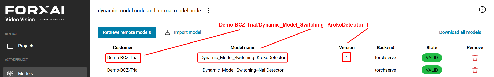 Model name syntax from Models page | String |
Outputs (packed) | Description | Type |
Prediction | Returns all attributes as a single prediction value. Individual attributes need to be extracted via the Extract Attribute node. | Prediction |
Outputs (unpacked) | Description | Type |
Heatmap | Displays the location of all the annotations in the dataset so you can see where they are most commonly positioned. | Heatmap |
Points | The list of all points in the model. | Point list |
Polygons | The polygons of the detected objects. | Polygon list |
Class | The text label of the prediction class. This label is defined during the model creation process. | String |
Probability | The probability of a correct detection as a number (0-1 where 0 represents 0% and 1 represents 100%). | Number |
Current_model | Returns the name of the currently used model, or an error message when the model isn’t registered. For more information, refer to the section below. | String |
The available outputs depend on the selected model.
The Current_model output of the Dynamic AI Model node provides the name of the currently active model, which can be displayed on the dashboard using the Text output node with a Value widget. This is useful for keeping track of which AI model is being used.
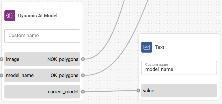
Displaying the active model name on the dashboard with the Text output node
Display behavior on the Dashboard
Normal operation
When the node is configured correctly, the dashboard will display the name of the active model.
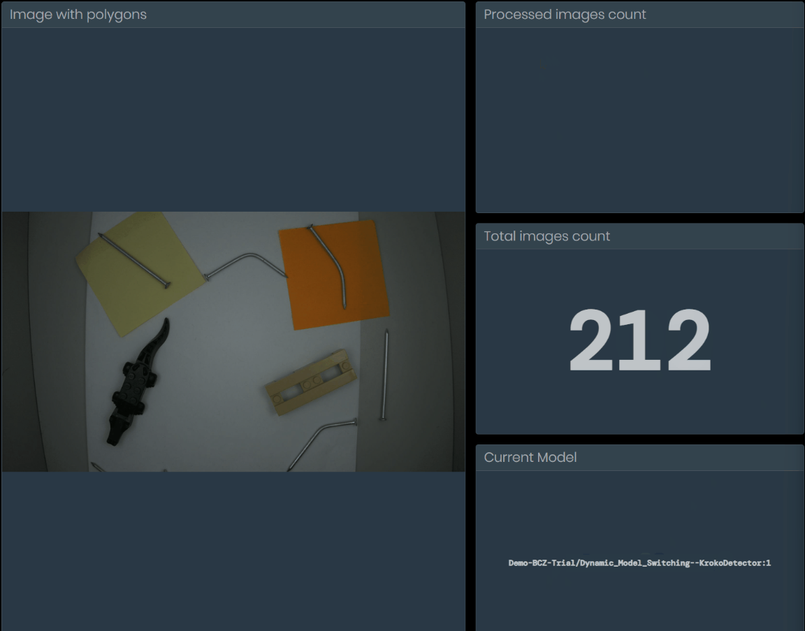
Dashboard displaying active model name
"No model registered" message
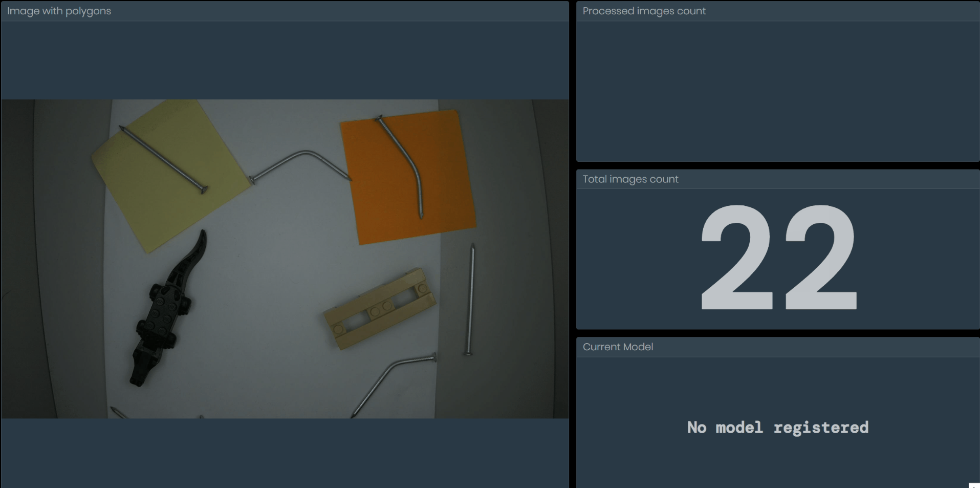
Dashboard displaying the “No model registered” error message
This message can appear on the dashboard under the following conditions:
The node is in its default state (e.g., upon deployment initialization or after a deployment configuration reset) and has not yet received a model name.
The received model_name input doesn’t match any of the selected model names (e.g., contains a typo or an error). When this occurs, the currently registered model is unregistered and awaits the next model_name input.
If "No model registered" appears on the dashboard:
Be aware that the message might temporarily appear during system initialization or after a deployment configuration reset. This is normal behavior and resolves once a model is received by the node in the model_name input.
Verify that all strings sent into the model_name input match the name of the selected models.
This section shows examples of how to send strings to the Dynamic AI Model node to select which model to load. These examples cover common ways to switch models during runtime.
Example - REST API request:
You can send the model name via a REST API request.
Prerequisites:
An external Connection to the server.
A String Input node.
Mapping the String Input node to the connection in Deployments.
The string input node must be set as Optional in Deployments.
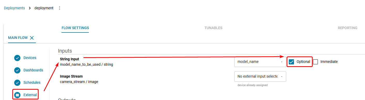
Setting the String Input as optional in Deployments.
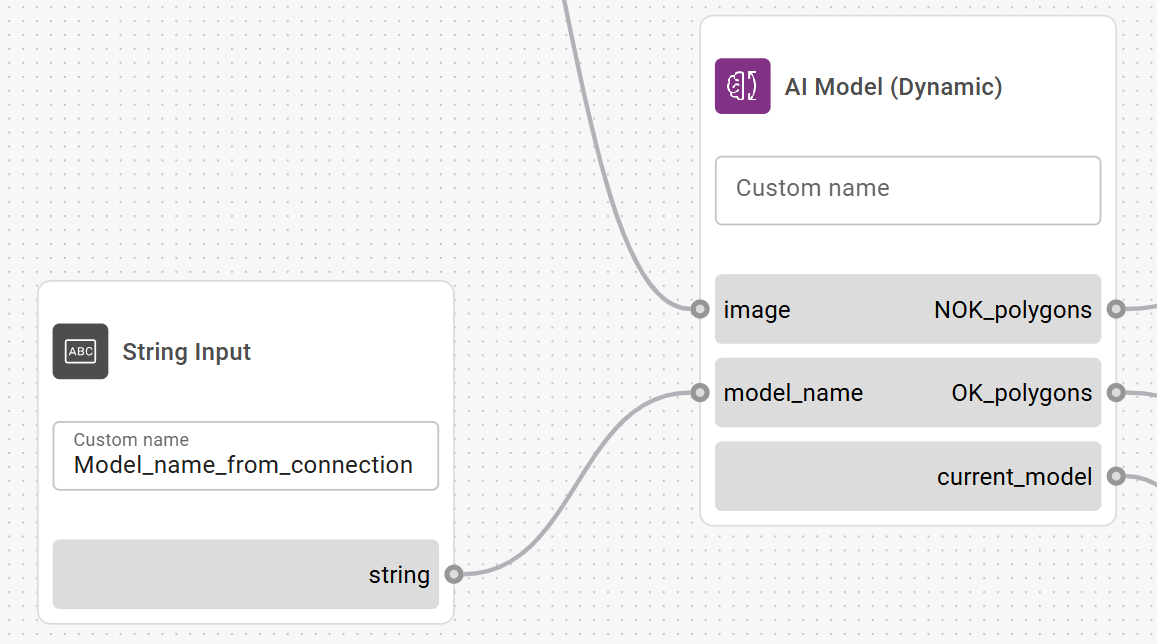
Example configuration to achieve model switching via external REST API requests
Example JSON string:
curl -k -X "POST" 'https://server_url/hashi/v1/http/external/input/project_id/name_of_created_external_connection' -H 'X-MQ-Payload-Type: string' -H 'Content-Type: application/json' -d '{"value":"MODEL_NAME"}' -H 'X-Correlation-ID: dce5d400-7513-4afb-bb90-716b2cc86fd7'Model Processors
Model processor nodes handle the data provided by the machine-learning model.

Annotate Polygons
The Annotate Polygons node highlights all input polygons of objects received from the previous node with a specific color and thickness.
The Annotate Polygons node is used to distinguish between different categories of identified items.
For instance, if an AI model is designed to detect goods with and without defects, you would use two Annotate Polygons nodes: one to color the polygons green and the other to color the polygons red. For customer solutions that need to detect just one object type, you would need only one Annotate Polygons node.
The Annotate Polygons node doesn’t draw polygons on the image. It only defines the attributes for the annotation, like color, opacity, and line thickness. To display the annotation on the image itself, the output polygons need to lead to a Draw Polygons node.
Configuration
Color
Sets the color for the input polygons.Line thickness
Sets the width of the polygon edges in pixels.Opacity
Sets how transparent the polygon is. 0% = fully transparent, 100% = fully opaque.
Inputs | Description | Type |
|---|---|---|
Polygon list | Received polygons. | Polygon list |
Outputs | Description | Type |
Annotated p. list | Returns the polygons modified according to the configuration. | Polygon list |

Count Polygons
The Count Polygons node counts the number of detected objects in an image. This node is mainly used to output the total number of polygons to the dashboard via the Number Output node.
Inputs | Description | Type |
|---|---|---|
Input | Receives polygons. | Polygon list |
Outputs | Description | Type |
Output | Returns the number of detected polygons. | Number |

Draw Polygons
The Draw Polygons node creates a visible overlay of annotated polygons on the image.
Configuration
Number of inputs
The number of polygon inputs to be merged. All the inputs must have a connection.
Inputs | Description | Type |
|---|---|---|
Input image | Receives the base image. | Image |
Polygon list | Receives the polygons to be drawn. | Polygon list |
Outputs | Description | Type |
Output image | Returns the image with the drawn polygons. | Image_svg |
To set apart different types of polygons with unique colors, you need to have the Annotate Polygons node at an earlier point in the flow. Otherwise, all polygons in the image will have the same default color and line thickness.
Adding polygons to an image changes its file type. Because of this, polygons can be added to an image only once.
Dynamic Selector
The Dynamic Selector node converts input values to new output values according to predefined configurations. It supports different value types, making it useful for tasks such as mapping specific identifiers to numerical data, or converting between types such as strings and booleans for further processing in production workflows.
Configure this node before connecting it to other nodes to set the correct input and output types.
Configuration
Input value type
Sets the type of the incoming data that will be converted. Supported types include string, number, integer.Output value type
Sets the type to which the input data will be converted. Supported types include string, number, integer, and boolean.
Once you set the value types, click Add Row to define specific input values and their corresponding output values. For example, you can map the string "bread" to a numeric weight or a product ID.
Example configuration
Inputs | Description | Type |
|---|---|---|
Key | The input value to be converted. | Defined by configuration |
Outputs | Description | Type |
Value | Outputs the converted value. | Defined by configuration |

Extract Attributes
Extracts a desired attribute from the AI Model node for further processing.
Configuration
Name of extracted attribute
The selected attribute will be extracted from the AI model.
Inputs | Description | Type |
|---|---|---|
Input | First polygon input. | Undefined |
Outputs | Description | Type |
Extracted | Returns the attribute selected in the configuration. | Matches selected attribute |
To be able to extract the AI model attributes, the AI Model node needs to have the outputs set to ‘mapped’.

Merge Polygons
The Merge Polygons node merges multiple polygon lists into one.
Configuration
Number of inputs
The number of polygon inputs to be merged. All the inputs must have a connection.
Inputs | Description | Type |
|---|---|---|
Input polygons 1 | First polygon input. | Polygon list |
Input polygons 2 | Second polygon input | Polygon list |
Outputs | Description | Type |
Merged polygons | Returns the merged polygons. | Polygon list |

Resize Polygons
Resizes polygons by adjusting their vertical and horizontal dimensions. The polygons are resized from the center.
Configuration
Horizontal scale
Changes the horizontal scale of the polygons. Values greater than 100% make the polygons bigger, while values lower than 100% make them smaller.Vertical scale
Changes the vertical scale of the polygons. Values greater than 100% make the polygons bigger, while values lower than 100% make them smaller.
Inputs | Description | Type |
|---|---|---|
Polygons | Receives polygon input. | Polygon list |
Outputs | Description | Type |
Scaled polygons | Returns the scaled polygons. | Polygon list |

Track Objects
The Track Objects node is used in customer use cases where items need to be tracked while moving (e.g., on a conveyor belt).
Configuration
Maximum stale track age
The time after which the object will stop being tracked if it leaves the detection area. If the object returns to the area after this time, it will be registered as a new object (classified as untracked). This setting is used to prevent false positives in cases where the object returns to the detection area shortly after leaving it (e.g., a conveyor belt that goes both directions).Maximum prediction distance difference
The node predicts the position of the object based on its previous trajectory. This setting sets the maximum allowed difference between the predicted position and the real-world position of the object. The maximum distance is configured in decimals that represent percentages, i.e., 0.2 = 20% of the image. With these settings, the maximum allowed difference between the predicted and actual positions is 20%. The main purpose of this node is to avoid false detections caused by random errors that might cause the objects to be detected in areas where they aren't actually present.Minimum detection hits
How many times the object needs to be detected in the image to get tracked (i.e., get classified as 'new'). When the number of configured detections is reached, the object is switched from 'untracked' to the 'new' category. For example, if you configure minimum hits as 3, the first two times the object is detected will categorize it as 'untracked', and the third hit will categorize it as 'new'.
Inputs | Description | Type |
|---|---|---|
Polygons | Receives polygons. | Polygon list |
Outputs | Description | Type |
Already tracked | Polygons that have been detected as new once before. | Polygon list |
Untracked | Polygons that have crossed the Minimum detection hits threshold in the configuration. | Polygon list |
New | Polygons that have crossed the untracked threshold and are detected for the first time. | Polygon list |
The node can only track objects going in one direction. When the objects change direction, they are registered as new objects.
Filters

Boolean Trigger
The Boolean trigger node only passes the input through if a condition is True.
This node is used, e.g., if you only want to process the image when the detected object is present in the image or when a button is pressed
Input | Description | Type |
|---|---|---|
Input | Receives any value. | Any |
Trigger | If the input value is true, the input is sent to the output. If it’s false, it is ignored. | Bool |
Output | Description | Type |
Output | Returns the input if the condition is true. | Any |

Condition
The condition node checks if a condition is true or false and then forwards the input if it is true.
Input | Description | Type |
|---|---|---|
Input | Receives any value. | Any |
Condition | If the input value is true, the input is returned through ‘then’ output. If it's false, the input is returned through ‘else’ output. | Bool |
Output | Description | Type |
Then | Returns the input if the condition is true. | Any |
Else | Returns the input if the condition is false. | Any |

Consecutive Trigger
The Consecutive Trigger node waits until enough positive (True) inputs are received. Once the number is reached, all positive inputs are passed through. Negative inputs reset the process.
Configuration
Required consecutive inputs
Sets how many consecutive positive inputs are required to pass the input through. A value of 1 passes all inputs through.Enable automatic state reset
If set to True, the count of positive inputs will reset to 0 each time this flow state becomes inactive.
Input | Description | Type |
|---|---|---|
trigger_in | Receives boolean values. | Bool |
Output | Description | Type |
trigger_out | Returns boolean values based on the configuration. | Bool |

Construct a List
The Construct a List node generates a list by combining multiple inputs, where each input becomes an item in the list.
The supported value types are String, Number, Bool, and Polygon. All inputs must be of the same value type.
Configuration
Number of inputs
Sets the number of possible inputs used to create the list.
Input | Description | Type |
|---|---|---|
input_0x | Individual input for the list. All inputs must be of the same value type. | Undefined |
Output | Description | Type |
output | Outputs a list of all the input values. | List of same value types as input |

Event Trigger
Only returns a positive value when the input value changes from negative to positive. Subsequent positive inputs are returned as negative.
Input | Description | Type |
|---|---|---|
trigger_in | Receives boolean values. | Bool |
Output | Description | Type |
trigger_out | Returns boolean values. | Bool |

Heatmap Threshold
The Heatmap Threshold node sets a threshold to highlight areas of an image as a heatmap. Areas meeting the threshold are shown in white, while those exceeding it are shown in black.
Configuration
Heatmap threshold
Input | Description | Type |
|---|---|---|
heatmap | Receives the heatmap. | Image |
Output | Description | Type |
binarymap | Returns boolean values. | Image |

Interval Filter
Sets a time delay between positive inputs.
When a positive (True) input is passed through, all subsequent inputs are returned as negative until the timer ends.
Configuration
Interval duration
The duration of the time window during which all positive triggers are returned as negative.
Input | Description | Type |
|---|---|---|
trigger_in | Receives boolean values. | Bool |
Output | Description | Type |
trigger_out | Returns boolean values. | Bool |

Isolate Polygon
Separates a single polygon from multiple polygons based on the attributes selected in the configuration.
Configuration
Polygon attribute
The attribute to filter a polygon by.Area
The area of the polygon.Probability
The AI model probability value associated with the polygon.
Value
The highest or lowest value of the selected attribute.Min
The lowest value.Max
The highest value.
Input | Description | Type |
|---|---|---|
Input | Receives polygons. | Polygon |
Output | Description | Type |
Output | Returns a polygon according to the configuration. | Polygon |

Polygon Threshold
The Polygon Threshold node filters out polygons based on the configuration.
Configuration
Minimum polygon area
The polygon area needs to be at least this % of the total image to pass through. Polygons smaller than this value are ignored.Probability threshold
The polygon probability needs to be at least this high to pass through.
Input | Description | Type |
|---|---|---|
Input | Receives polygons. | PolygonList |
Output | Description | Type |
Output | Returns polygons based on the configuration. | PolygonList |
Logic

AND
The AND node is a Logic gate. A logic gate takes input signals and produces an output based on rules specific to the gate.
For AND, if all inputs are true, the output is true (signal is passed). Otherwise, the output is false (signal is blocked).
Configuration
Number of inputs
The number of available inputs.Ignore Nothing values as inputs
True
Any ‘Nothing’ value type inputs are ignored.False
If any input is a ‘Nothing’ value type, the node output is Nothing.
Result when no inputs have values
True
When all inputs are ‘Nothing’ value type, the output is true.False
When all inputs are ‘Nothing’ value type, the output is false.
Input | Description | Type |
|---|---|---|
Input 1 | Receives input signals. | Bool |
Input 2 | Receives input signals. | Bool |
Output | Description | Type |
Output | Emits a true or false value based on the inputs and the node configuration. | Bool |

Boolean to Text
The Boolean to Text node transforms boolean values (true/false) to a text output of your choice.
Usage example: If you want the dashboard to display “OK” or “Faulty” for each item that passes through the camera, you enter “Faulty” in the Negative value field and “OK” in the Positive value field. Then, you connect a node with a ‘bool’ value type output (e.g., Compare Value) to the input of Boolean to Text, and you connect the output of Boolean to Text to a Text Output node.
Configuration
Negative value
Outputs the set text when the input is ‘false’.Positive value
Outputs the set text when the input is ‘true’.
Input | Description | Type |
|---|---|---|
Input | Receives a bool value. | Bool |
Output | Description | Type |
Output | The text output (both positive and negative value depending on the input). | String |

Compare value
The Compare Value node compares inputs via mathematical operators and outputs a True or False value based on the result.
For instance, if you configure the node to “>= 15”, it will output a false value until the input signal is 15 or higher, at which point it will output a true value.
Configuration
Comparison value
The value to which the input is compared.Operator
Compares the input based on mathematical operators.
Input | Description | Type |
|---|---|---|
Input | Receives input signals. | Any |
Output | Description | Type |
Output | Returns a true or false value based on the node configuration. | Bool |
The node can also be used to compare text inputs (or Booleans transformed to text) with the operators == (equals) and != (doesn’t equal).

Division
The Division node divides an input number (numerator) by a second input number (denominator), then outputs the result.
Input | Description | Type |
|---|---|---|
Numerator | The number that will be divided. | Number |
Denominator | The number by which the numerator is divided. | Number |
Output | Description | Type |
Output | Returns the result of the division operation. | Number |

NAND
The NAND node is a Logic gate. A logic gate takes input signals and produces an output based on rules specific to the gate.
NAND is an AND gate followed by a negation (the signal is inverted). For NAND, if any inputs are true, the output is false (signal is blocked). Otherwise, the output is true (signal is passed).
Configuration
Number of inputs
The number of available inputs.Ignore Nothing values as inputs
True
Any ‘Nothing’ value type inputs are ignored.False
If any input is a ‘Nothing’ value type, the node output is Nothing.
Result when no inputs have values
True
When all inputs are ‘Nothing’ value type, the output is true.False
When all inputs are ‘Nothing’ value type, the output is false.
Input | Description | Type |
|---|---|---|
Input 1 | Receives input signals. | Bool |
Input 2 | Receives input signals. | Bool |
Output | Description | Type |
Output | Emits a true or false value based on the inputs and the node configuration. | Bool |

NOR
The NOR node is a Logic gate. A logic gate takes input signals and produces an output based on rules specific to the gate.
NOR is an OR gate followed by a negation (the signal is inverted). For NOR, if any of the inputs are true, the output is false (signal is blocked). Otherwise, the output is true (signal is passed).
Configuration
Number of inputs
The number of available inputs.Ignore Nothing values as inputs
True
Any ‘Nothing’ value type inputs are ignored.False
If any input is a ‘Nothing’ value type, the node output is Nothing.
Result when no inputs have values
True
When all inputs are ‘Nothing’ value type, the output is true.False
When all inputs are ‘Nothing’ value type, the output is false.
Input | Description | Type |
|---|---|---|
Input 1 | Receives input signals. | Bool |
Input 2 | Receives input signals. | Bool |
Output | Description | Type |
Output | Emits a true or false value based on the inputs and the node configuration. | Bool |

NOT
The NOT node is a Logic gate. A logic gate takes input signals and produces an output based on rules specific to the gate.
For NOT, any input is inverted. If the input is true, output is false and vice versa.
A NOT gate only supports a single input.
Input | Description | Type |
|---|---|---|
Input | Receives input signals. | Bool |
Output | Description | Type |
Output | Emits a true or false value based on the inputs and the node configuration. | Bool |

OR
The OR node is a Logic gate. A logic gate takes input signals and produces an output based on rules specific to the gate.
For OR, if any of the inputs are true, the output is true (signal is passed). Otherwise, the output is false (signal is blocked).
Configuration
Number of inputs
The number of available inputs.Ignore Nothing values as inputs
True
Any ‘Nothing’ value type inputs are ignored.False
If any input is a ‘Nothing’ value type, the node output is Nothing.
Result when no inputs have values
True
When all inputs are ‘Nothing’ value type, the output is true.False
When all inputs are ‘Nothing’ value type, the output is false.
Input | Description | Type |
|---|---|---|
Input 1 | Receives input signals. | Bool |
Input 2 | Receives input signals. | Bool |
Output | Description | Type |
Output | Emits a true or false value based on the inputs and the node configuration. | Bool |

Sum
The Sum node adds up all the numerical inputs and then outputs them as a sum. The node doesn’t store any previous values; all new inputs are added up once.
Configuration
Number of inputs
Sets the number of available inputs. All inputs must be connected in order for the node to function.
Input | Description | Type |
|---|---|---|
Number1 | Receives the first number to be added up. | Number |
Number2 | Receives the second number to be added up. | Number |
Output | Description | Type |
Output | The added-up number. | Number |

XOR
The XOR node is a Logic gate. A logic gate takes input signals and produces an output based on rules specific to the gate.
For XOR, if exactly one of the inputs is true, the output is true (signal is passed). Otherwise, the output is false (signal is blocked).
Configuration
Number of inputs
The number of available inputs.Ignore Nothing values as inputs
True
Any ‘Nothing’ value type inputs are ignored.False
If any input is a ‘Nothing’ value type, the node output is Nothing.
Result when no inputs have values
True
When all inputs are ‘Nothing’ value type, the output is true.False
When all inputs are ‘Nothing’ value type, the output is false.
Input | Description | Type |
|---|---|---|
Input 1 | Receives input signals. | Bool |
Input 2 | Receives input signals. | Bool |
Output | Description | Type |
Output | Emits a true or false value based on the inputs and the node configuration. | Bool |
Aggregators

Accumulator
The Accumulator node adds up and stores the numeric value received in the ‘Input’ connection.
The stored value can be reset to zero upon receiving any signal in the ‘reset’ connection.
The Accumulator node only supports one input. To add up multiple numbers, you need to use the Sum node.
Configuration
Enable automatic state reset
If set to True, the count of positive inputs will reset to 0 each time this flow state becomes inactive.
Input | Description | Type |
|---|---|---|
Input | Any received number is added to the current value stored in the node. | Number |
Reset | Resets the stored value to 0. | Any |
Output | Description | Type |
Value | The current value that is stored in the node. | Number |

Counter
The Counter node counts the number of input signals received. This can be used for counting the instances of receiving, e.g., defects, images, or polygons. Every new input increments the current value stored in the node by 1.
Configuration
Reset threshold
The counter is reset upon reaching the set value.Enable reset input
If set to True, adds a new ‘reset’ input, which allows the counter to be reset by a signal from another node.Enable automatic state reset
If set to True, the count of positive inputs will reset to 0 each time this flow state becomes inactive.
Input | Description | Type |
|---|---|---|
Input | Any input increments the current value stored in the node by 1. | Any |
Reset | Any input resets the stored value to 0. | Any |
Output | Description | Type |
Counter | The current value that is stored in the node. | Number |
The Counter node only counts received inputs (signals). It doesn’t handle the contents of the input message (e.g., if the Counter node receives number 450 as input, it will only add 1 to the count, as it is just one message). To count the numerical contents of messages, use the Accumulator node.
Get Shared Memory and Set Shared Memory
The ‘Get Shared Memory’ and ‘Set Shared Memory’ nodes work together to temporarily store and retrieve data.
The ‘Set Shared Memory’ node saves input data using a defined ‘key,' allowing the 'Get Shared Memory’ node to later access this value by referencing the same key. This connection enables data continuity and data transfer between nodes and flows.
Configuration
Memory key
Sets the identification key used to link the nodes.Enable automatic state reset
When set to ‘True’, resets the node when the flow state resets.Value type
Sets the type for the stored value. The type must match for both linked nodes.
Set Shared Memory I/O
Input | Description | Type |
Input | Saves the input in the memory storage. | Defined by config |
Get Shared Memory I/O
Output | Description | Type |
Value | Returns the value from the memory storage. | Defined by config |
Miscellaneous
This category contains various nodes without a specific category.

Barcode Reader
The Barcode Reader node detects barcodes on the image input and outputs values detected in the barcode.
Configuration
Code type
Sets the node to only detect a specific barcode type.Number output
Changes the ‘value’ output type to number.
Input | Description | Type |
|---|---|---|
Image | Receives an image used to detect a barcode. | Image |
Output | Description | Type |
Value | The code value of the barcode. Can be output either as a string or as a number type based on node configuration. | String |
Polygon | Outputs a polygon of the outline of the barcode. | PolygonList |
Quality | Numerical value of the quality of the detection (e.g., a barcode on a flat piece of paper will have a higher value than crumpled food packaging.) This output is currently not relevant to any deployments. | Number |
Orientation | Orientation of the code relative to the camera (Up, Down, Left, Right). | String |
When multiple barcodes are present in the image, the node only detects the best readable one. All other barcodes are dismissed.

Change Flow
The Change Flow node is used to switch to a different, preconfigured state (represented by a flow). The change to the new flow is triggered by either a bool input with a True value or on all other inputs of any value type.
Input | Description | Type |
Trigger | Switches to the new state upon receiving a signal. | Any |

Hold
Temporarily delays the input for a set amount of time.
Configuration
Wait always
When set to True, the node will always wait for “Nothing” value type inputs. When set to False, it will wait for all value types except “Nothing”.Wait time
Sets the delay duration.
Input | Description | Type |
|---|---|---|
Input | The input to be delayed. | Any |
Output | Description | Type |
Output | The delayed value from input. | Same as input |

Table statistics
Structures data sets into rows and columns.
Configuration
Pre-specified inputs
Labels the rows of the table that represent inputs. The inputs need to be separated by a comma (e.g. Good items, Defective items).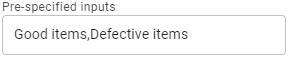
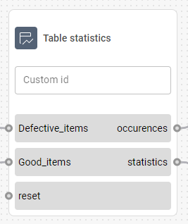
Statistics method
Determines which statistical value will be displayed for each input row.Sum
The total sum of all the input signals.Average
The average of all received values.Min
The lowest received value for the respective inputs.Max
The highest received value for the respective inputs.
Input | Description | Type |
|---|---|---|
Reset | Resets all values in the table upon receiving a signal. | Any |
Classification | String | |
Value | Number | |
Output | Description | Type |
Statistics | Displays the value set in the ‘Statistics method’ option in the configuration. | Table |
Occurences | Displays the number of all inputs. | Table |

Timer
The timer node triggers an event after a set period of time.
This node can be used for, e.g., delaying the processing of the image to give lights enough time to activate.
Configuration
Countdown
Sets the period of time (in seconds) that starts counting down once the Start input is triggered.Emit events before timeout
When selected, the Event output will continually emit a ‘false’ signal.
Input | Description | Type |
|---|---|---|
Start | Starts (or restarts) the timer upon receiving a bool input with a True value. When receiving a number input, it starts the timer and sets the countdown time according to the number in the input. | Any |
Stop | Pauses the timer until the Resume input is triggered. For bool input types, the timer is only stopped if the value is True. | Any |
Resume | Resumes the timer if it’s paused. | Any |
Output | Description | Type |
Event | Triggers an event when the timer runs out. | Bool |
Running | Emits whether the timer is currently running or not. | Bool |
Remaining | The remaining time (in seconds) before the event occurs. If the timer is not running, nothing is emitted. | Number |
Outputs
All output nodes serve as endpoints of the flow.
These nodes can be used to:
display information on the customer dashboard
transfer data to another flow

Boolean Output
The Boolean Output node receives a bool value from the flow to make it displayable on the customer dashboard.
Input | Description | Type |
Value | Receives a boolean value to display on the dashboard. | Boolean |

Capture Flow
The Capture Flow node is used to trigger data collection for Reporting.
When this node receives a True boolean signal, it records data from all Output nodes in the flow, provided those nodes are marked for reporting in the Deployment settings. If the received signal is False or absent, none of the selected outputs are stored.
For example, you can collect flow data only when specific conditions are met, such as detecting a defect or exceeding a certain value threshold.
The Capture Flow node only captures outputs that are selected in the Deployment configuration.

Date & Time
The Date & Time output node receives date and time from the flow to make it displayable on the customer dashboard.
Input | Description | Type |
Value | Receives the date and time data to display on the dashboard. | Datetime |

Image
The Image output node receives an image from the flow to make it displayable on the customer dashboard.
Input | Description | Type |
Value | Receives an image to display on the dashboard. | Image, ImageSvg |

Number
The Number output node receives a number from the flow to make it displayable on the customer dashboard.
Input | Description | Type |
Value | Receives a number to display on the dashboard. | Number |

Point List
The Point List output node is used to output a point list to a different flow.
Input | Description | Type |
Value | Receives a point list to transfer to a different flow. | Point list |

Polygon
The Polygon output node is used to output a point list to a different flow.
Input | Description | Type |
Value | Receives a polygon to transfer to a different flow. | Polygon |

Table
The Table output node receives collected statistics in a table grid to make it displayable on the customer dashboard.
Input | Description | Type |
Value | Receives a table input to display on the dashboard. | Table |
This node only accepts output from the Table statistics node.

Text
The Text output node receives text from the flow to make it displayable on the customer dashboard.
Input | Description | Type |
Value | Receives a text to display on the dashboard. | String |